


What Is an RF Attenuator and How Does It Work?
An RF attenuator is a passive two-port part that lowers RF signal power by an exact, set amount measured in decibels (dB). Its main job is simple: bring the signal level down without really changing the waveform. You will find these parts protecting sensitive test tools, like spectrum analyzers, from overload. They also match signal levels between stages so each block gets what it expects. A wrong value can clip a receiver or hide a weak measurement. This article explains the working principle behind rf attenuators, the main types, the key specifications, and how to choose an attenuator for your setup.
Key Takeaways
An RF attenuator is a passive part that lowers signal power by an exact amount in decibels.
It works by taking in signal energy in resistors and turning it into heat without changing the waveform.
Fixed attenuators give steady values, while variable and step types let you change them during tests.
The main specs to check are frequency range, attenuation value, power handling, and VSWR.
Make sure the attenuator matches your system impedance, and test it in your setup before you buy.
What Is an RF Attenuator?
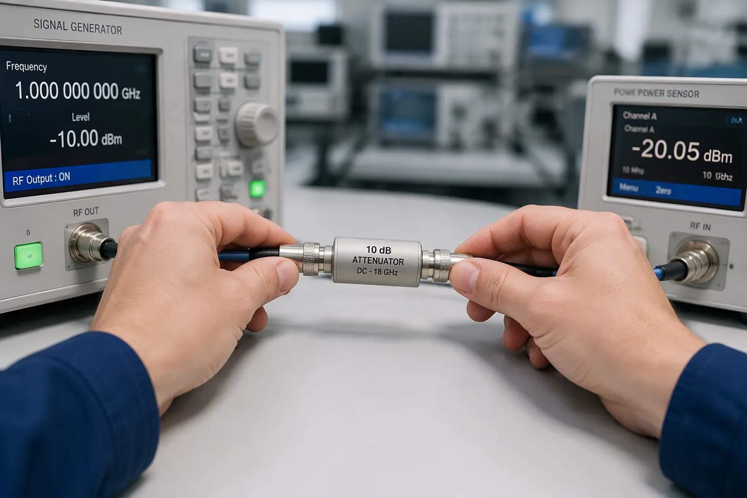
Definition and Core Function
An RF attenuator is a passive, two-port part. It takes in or soaks up some of the energy and lowers the signal strength in a controlled way. Think of it as the opposite of an amplifier. An amplifier adds gain, but an attenuator adds loss and keeps gain below one. The device lowers the power or strength of an RF signal by an exact amount. That amount is measured in decibels, or dB. You figure out the attenuation value you need from the gap between your source level and the highest input the next part can take. This way, the attenuator matches a bigger level at one point to a smaller limit at another stage.
The core function is more than just lowering the level. An attenuator also makes the impedance match better between a source and a load. It can hide poor VSWR conditions and keep circuit stages apart. This separation and buffering stops reflected energy from harming the source or causing instability. Attenuators also step down known amounts for calibration and leveling. A good pad keeps the chain steady and predictable. The question what is rf attenuator comes up often in test labs, and the answer usually starts with this idea of controlled loss. You get exact control of signal strength at a transmitter output or before a sensitive receiver.
Why Attenuation Matters
You will run into signal attenuation in many real situations. Transmitter testing is one clear case. A calibrated attenuator lowers the signal strength before the power sensor, so the sensor survives the test. Calibration labs use attenuators to scale down a level and find true power through the attenuation factor. General RF measurement relies on the same idea. Most energy turns into heat, and the sensor reads a scaled-down level. This approach protects equipment while keeping wideband capability from MHz to GHz. The pad also gives you a known reference point for comparing runs over time.
Protection is the main benefit. Sensitive receivers and spectrum analyzers have a top input limit. A level above that limit can clip or destroy the front end. A pad placed ahead of the instrument soaks up the extra. Level matching is the second benefit. Each stage in a chain expects a certain range. These parts let you feed the right level to each block. Preventing overload follows naturally. A pad at the input and output of reflective parts, such as filters and mixers, lets reflected voltage fade quickly instead of building into a standing wave. This simple part adds little cost and takes almost no bench space.
Impedance matching deserves its own note. Attenuators make the match better between port impedances that don't agree. They lessen how much reflections matter between ports that don't match well. This buffering role keeps a chain stable. You can also use attenuators to lower the signal strength in a calibration step with a source. That step ensures an exact level at the output of a test system. For these reasons, rf attenuators show up in test and measurement, telecom, and defense setups. These parts serve RF test benches and RF systems in many industries. Engineers reach for rf attenuators whenever a source is too hot for the next stage.
How Does an RF Attenuator Work?
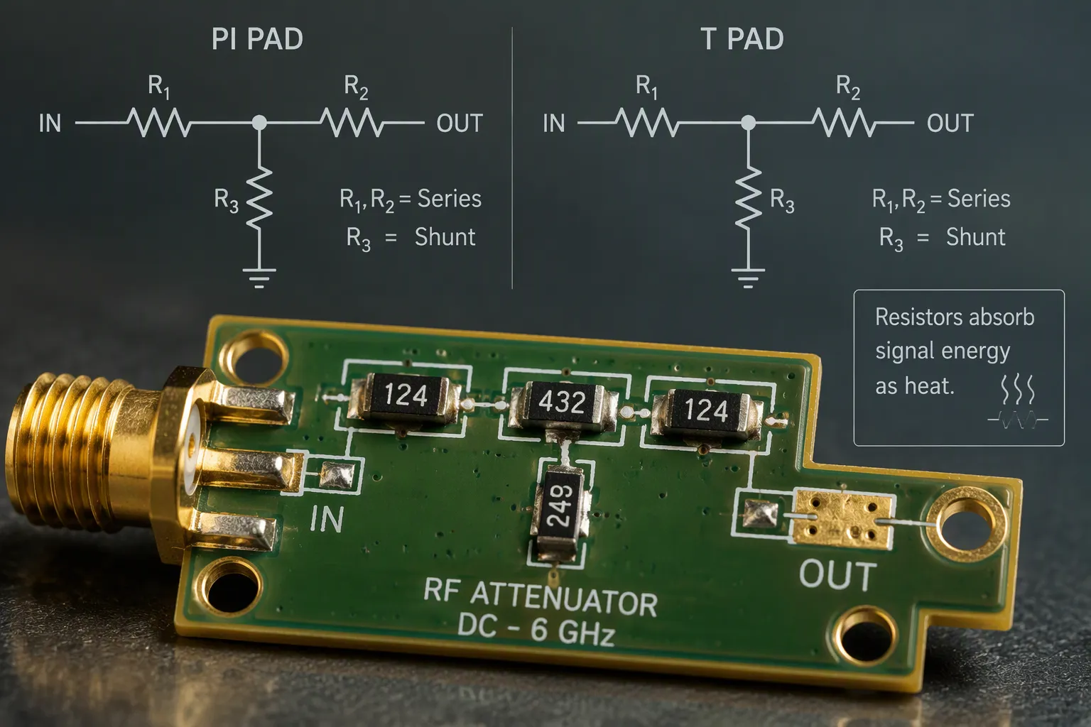
Attenuation Mechanisms
An rf attenuator works by soaking up signal energy in resistors. The signal enters a resistor network and leaves as heat. The resistors turn electrical energy into thermal energy instead of bouncing it back. This lowers the power or amplitude of an rf signal in a steady, predictable way. You get a clean drop with no added gain and no change to the waveform.
A simple resistor network is the heart of every rf attenuator circuit. Designers use two common layouts: the PI pad and the T pad. Each layout sets the attenuation level through specific resistor values. The table below compares them.
Aspect | PI pad | T pad |
|---|---|---|
Network structure | Two shunt arms plus one series arm | Two series arms plus one shunt arm |
Good starting point when | Fixed attenuation and a clean low-inductance ground are available | A single shunt connection is easier and series values are practical |
Primary design risk | Shunt-via and ground inductance degrade high-frequency match | Series package and trace inductance plus the central shunt return path |
Example at 3 dB, 50 Ω | About 17.6 Ω series, about 292 Ω each shunt | About 8.55 Ω each series, about 141.9 Ω shunt |
Both topologies are electrical duals. They give the same nominal attenuation and port impedance for equal source and load. Neither is always better. You pick based on buildable values, a clean RF current path, and lower parasitic sensitivity.
A T-pad is recommended for low-impedance systems (such as 50Ω RF or 8Ω audio) because it keeps the series resistor values close to Z0, thereby avoiding extremely small shunt resistor values.
For example, a 6 dB T-pad in a 50-ohm system uses series resistors of about 16.6 ohms and a shunt resistor of about 66.5 ohms. This spread keeps each part easy to build.
Impedance Matching and Design
The attenuator must match the system impedance, usually 50 ohms. This match cuts reflections and keeps the waveform shape intact. An rf attenuator circuit that matches its ports soaks up incoming energy cleanly. Mismatched ports send energy back to the source and mess up the signal.
Why does 50 ohms dominate? The standard goes back to 1930s coax cables built for kilowatt radio transmitters. Engineers needed a compromise among three goals:
Lowest loss, near 77 ohms for air-filled coax
Highest voltage handling, near 60 ohms
Highest power transfer, near 30 ohms
No single value meets all three. 50 ohms sits close to the mean of 77 and 30, and near 60. It balances low loss, good power handling, practical size, and easy matching. That balance explains its use in wireless communication, RF test equipment, radar, antennas, and RF PCB and coaxial cables.
Good design also controls parasitics. Shunt elements need short, low-inductance ground paths. Series elements need short, symmetric traces. These layout choices keep the match stable at high frequency and protect the waveform.
Types of RF Attenuators
Fixed and Variable Attenuators
You can divide attenuator types into two main groups: fixed or variable. A fixed attenuator keeps one value for its whole life. Fixed attenuators usually cover 1 dB to 30 dB or more, and some designs reach DC to 110 GHz. That steadiness makes them the top pick for repeatable bench setups and production test. A variable attenuator lets you change the level during a test. Continuously variable attenuators sweep smoothly across a range. Voltage variable attenuators change value with a control voltage, so they fit automatic leveling loops. Both styles meet real needs, and neither takes the place of the other.
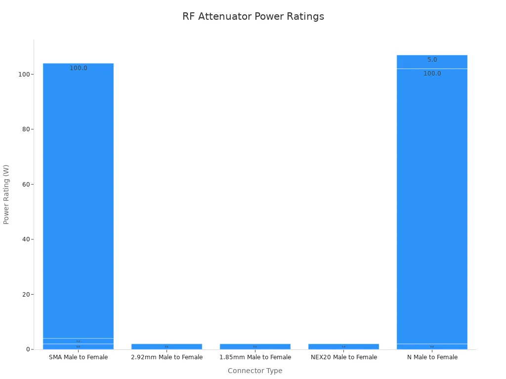
Teruilai's RF Fixed Attenuators show how far a fixed part can go. They come in SMA, N, BNC, and 2.92mm connectors, support frequencies up to 67 GHz, and handle power from 2W to 100W. The table below lists a few examples.
Connector Type | Power Rating | Frequency Range |
|---|---|---|
SMA Male to Female | 2W | 18 GHz |
2.92mm Male to Female | 2W | 40 GHz |
N Male to Female | 100W | 18 GHz |
Step and Programmable Attenuators
A digital step attenuator switches between set values in separate steps. You control it with logic lines, so a test system can change attenuation without touching hardware. A programmable attenuator adds remote control over a bus. These parts work best where a system must cycle through many levels fast. Radar and frequency-hopping systems care about switching speed, the time from a control change to a stable RF output. MEMS-based designs report closing times near 58.5 μs and opening times near 18.6 μs, with contact resistance under 0.65 Ω across many cycles.
Pick a fixed pad for stable, low-cost level setting. Pick a step or programmable unit when the test plan calls for many values in sequence. Each setup has a clear home in the lab.
Key Attenuator Specifications
Frequency, Attenuation, and Power
Three specs guide most of your choices: frequency range, attenuation value, and power handling. Start with frequency. Your attenuator has to cover the whole band you plan to test. Today's commercial rf attenuators reach up to 50 GHz, and some fixed ones go even higher. Look at the datasheet curve, not just the big number on the front. Performance often slips near the edges of the band.
Next is attenuation value in dB. You choose the value based on the gap between your source level and the top input of the next stage. Attenuation range and flatness count just as much as the nominal number. Flatness shows you how much the value moves across the band. A pad rated 10 dB that drifts a full dB at the top of the band will throw off your measurements.
Power handling sets the physical size and the cost. Soaked-up energy becomes heat, so a high-power pad needs a larger body and better paths for heat. Match the rating to your worst-case signal level, with room to spare. A 100W pad on a 2W signal wastes space and money.
VSWR, Impedance, and Connectors
VSWR shows you how well the ports match the system. Good-quality rf attenuators usually keep VSWR near 1.1:1 at lower frequencies and climb to about 1.2:1 higher up. The table below lists some typical values.
Device | Frequency | VSWR |
|---|---|---|
20 dB attenuator | 1 GHz | <1.1 |
20 dB attenuator | 2 GHz | <1.2 |
Feedthrough pad | 250 MHz | <1.1 |
Feedthrough pad | 500 MHz | <1.2 |
Impedance is next. Most systems run at 50 ohms, and your pad must match it so reflections don't happen. The connector you pick then limits your usable bandwidth. SMA works to about 18 GHz, N-type to roughly 11–12 GHz, and 2.92mm to about 40 GHz.
Precision grades matter: 2.92 mm reaches ~40 GHz, 1.85 mm to ~67 GHz, and 1 mm types extend to 110–120 GHz.
Weigh resolution, speed of adjustment, insertion loss and vswr together when you compare variable attenuators against fixed attenuators. Each spec trades off against the others.
Choosing the Right Attenuator
Matching Attenuator to Application
Begin with the job your setup has to do. A test and measurement bench needs tight accuracy, so a measurement system usually needs ±0.5–1.0 dB, while a fixed system may accept ±2–3 dB. Telecom and 5G chains care about steady level control across wide bands. Aerospace and defense work adds heat stress and long duty cycles. The table below shows how the main specs change by application.
Application | Frequency focus | Attenuation accuracy | Power handling |
|---|---|---|---|
Test and measurement | Wide band, up to 67 GHz | ±0.5–1.0 dB | Low to moderate |
Telecom | Band-specific | Moderate | Moderate |
Aerospace and defense | Wide band, harsh conditions | Tight | High |
5G | Sub-6 GHz and mmWave | Moderate to tight | Moderate |
Check that the frequency range covers your band with room to spare. Set the lowest and highest attenuation you need, including space for tolerances and temperature drift. Confirm the power rating against your worst-case input, because dissipated power equals input power times (1 – 10^(-Attenuation/10)). Match impedance to 50 ohms to avoid reflections that harm insertion loss and frequency response.
Selection Checklist
Use this list before you commit to a part:
Frequency range: pick a unit made for your band, with margin at both edges.
Attenuation level: confirm the value and how flat it stays across the band.
Power handling: compare calculated dissipation to the continuous rating.
Connectors: match SMA, N, BNC, or 2.92mm to your existing hardware.
Temperature stability: check specs across your operating range.
Verification: test a sample in your own setup before a bulk purchase.
Many users often miss these details, which leads to poor performance in their setups. Testing and understanding your specific needs is critical for getting the best results.
Teruilai supports standard or custom attenuation values, backed by professional technical support and a full after-sales system. That help matters when you need to select the right rf attenuator for an unusual band or power level.
An RF attenuator is a passive two-port part that lowers signal power by an exact amount in dB. It takes in energy through resistors and turns it into heat. The waveform stays the same, so your measurement stays accurate. Fixed, variable, step, and programmable attenuators each have a job. Fixed pads give steady attenuation values, while variable and step types let you adjust during a test.
RF attenuators come in many forms, but the same rules guide your choice. Frequency range, attenuation value, power handling, and VSWR decide if a part fits. Match all four to your application before you buy. Check the datasheet against your own setup, because a bench test tells you more than a spec sheet.
FAQ
What does an attenuator actually do to the signal?
It absorbs part of the energy and turns it into heat. The output level drops by a set amount in dB. The waveform shape stays the same. You get a smaller signal without distortion, and the next stage sees a level it can handle.
Why do I need 50 ohms instead of another impedance?
Most rf test gear and coax systems run at 50 ohms. A matching attenuator stops reflections at its ports. Reflections waste energy and distort the waveform. Check your system impedance first, then pick a pad built for it.
How do I pick the right attenuation value?
Measure the gap between your source level and the maximum input of the next stage. Choose a value that closes that gap with margin. Add a few dB of headroom for drift. Too little attenuation leaves the receiver at risk.
Can I use one attenuator across my whole frequency band?
Only if its datasheet covers that band with margin at both edges. Performance often slips near band limits. Connector type also caps usable range: SMA reaches about 18 GHz, and 2.92mm reaches about 40 GHz. Verify flatness before you commit.
Do fixed attenuators handle high power?
Some do. Teruilai's fixed attenuators range from 2W to 100W across SMA, N, BNC, and 2.92mm connectors, with support up to 67 GHz. Match the rating to your worst-case input. Dissipated heat equals input power minus output power, so high-power pads need larger bodies.


