How To Choose The Common 1.85mm Microwave connectors Correctly
 Dec 10, 2019|
 View:1118
How To Choose The Common 1.85mm Microwave connectors Correctly
In many RF and microwave applications, it is very important to choose the right connector. Proper selection, use, and maintenance can prolong the service life of the connector and optimize the system performance. For the novice in the microwave field, they often encounter different microwave connector selection problems.
It is often asked:
Can standard SMA be connected with standard 2.92?
What kind of connector is this special?
A: today, let's talk about the common high-frequency microwave connector. Here, we will find the answer you want.
Why are there different connectors?
A: many coaxial connectors will be used in RF and microwave fields. Each connector has a special purpose and application. One of the key points is to ensure the best performance and the maximum number of repeated connections.
Several common microwave connectors are introduced first
The N RF Fixed Attenuator was designed for Navy systems in the 1840s (named after Navy) and works within 5GHz. In the 1960s, the improved performance can reach 12GHz and then develop to 18GHz.
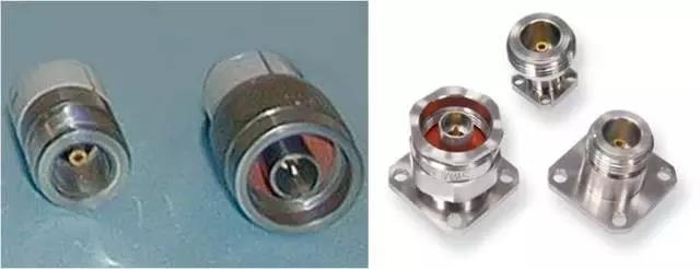
Male and male N RF Fixed AttenuatorMale and female N RF Fixed Attenuator for panel
BNC connector
BNC connector was originally designed for military applications (known as bayonet Navy connector). It uses a bayonet connection mode, which makes the connection quick and reliable. Working frequency can reach 4GHz, which is widely used in radio equipment, electronic instruments, network system interconnection, and military applications.
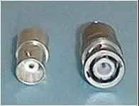
Male and male BNC connectors
TNC connector
TNC connector is a kind of threaded BNC. Because it can effectively solve the problem of signal leakage and connector stability of the BNC connector, the working frequency can reach 12GHz, and it is widely used in the connection of mobile phone microwave/antenna.
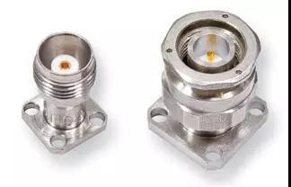
Male and male TNC connectors for panels
SMA Microwave Connectors were developed in the 1860s. it was designed by Bendix scintilla company and Omni spectrum company. The purpose of the design is to use it for the low-frequency connection of semi-rigid cables and devices. The design working frequency of the standard SMA connector is 12.4ghz, and better SMA can be used for 18GHz or even 24GHz. Some special high-quality SMA connectors produced by some manufacturers can reach 26.5ghz. SMA connector has become one of the most commonly used connectors in RF and microwave fields. However, limited by its structural design, its service life is only a few hundred times, which is suitable for the occasion of infrequent links.
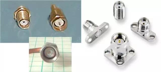
Male and male SMA Microwave Connectors Male and female SMA Microwave Connectors for panels
SMB connector
The sub-minimum B connector is a bayonet-type connector with a working frequency of 4GHz.
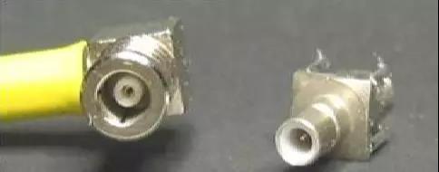
Female and male SMB connectors
GPO (SMP) connector
The working bandwidth of GPO connector is 40GHz, and the plug-in life varies from 100 to 1000 times based on different stop structures.
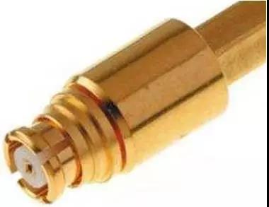
Female GPO connector
Gppo (SSMP) connector
Gppo connector is only 1 / 3 of GPO connector, and its working bandwidth is 65ghz.
Female Gppo connector
Let's talk about the compatibility of the precision SMA connector
In order to reduce the reflection coefficient and improve the connection performance, a variety of "precision SMA connectors" have been developed. At present, there are two basic structures (nonreal SMA connector), one is 3.5mm (Wilton wsma), the other is 2.92mm (Wilton K).
Do you have any questions?
When SMA and 3.5mm and 2.92mm connectors are connected to each other, there may be problems? What's the problem?
When SMA connector of male is inserted into 3.5mm or 2.92mm female connector, it may cause damage to female connector.
In fact, as long as the operation is standardized, the precision of 3.5mm and 2.92mm connectors can ensure the safety of the connectors. However, the precision of SMA male connector is relatively poor, especially if the SMA male connector is not properly aligned and straightened when it is connected, or the pin of SMA male connector is too long, it will seriously damage the 3.5mm or 2.92mm female connector. This is a point of special attention.
Special reminder:
When using SMA male connector cable, especially semi-rigid cable, if it is bent near the connector, it will lead to the change of the length of the pin in SMA male connector. Even if the "connection protector" (i.e. adapter) is used, it will push the pin in the connector, which will lead to the damage of 3.5mm or 2.92mm female connector interconnected with this cable connector.
The legend is as follows:
Before bending:

After bending: conductor protruding in the center

Therefore, when using SMA male connector to interconnect with "precision SMA female connector (3.5mm or 2.92mm)", it is necessary to ensure the professionalism of SMA male connector manufacturer, and ensure that the male connector is connected in a positive and straight direction.
3.5mm connector
The 3.5mm connector was first developed by Hewlett Packard (HP company, now Agilent) in the United States. Its size and specification are consistent with SMA. The difference is that the air medium is used in the connector, and the working frequency is 34GHz. Physical interfaces are more robust than SMA, enabling thousands of repeated connections. It is named 3.5mm connector due to its inner diameter of outer conductor is 3.5mm.
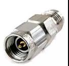
Male and male 3.5mm connectors
"K" and 2.92mm Microwave Connectors
The "K" connector was developed and designed by Wilton company (now Anritsu company) in 1983. It is also named K (the K-band whose working frequency covers the microwave band). Because of its inner diameter of outer conductor of 2.92mm, it is called 2.92mm Microwave Connectors. K connector can be connected with SMA, 3.5mm and other 2.92mm connectors (such as HP 2.92mm), with the working frequency of 40GHz and 46ghz. Some manufacturers also call this connector 2.9 or SMK connector.
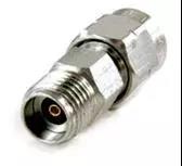
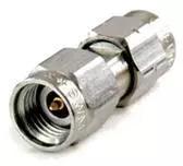
2.92mm male and male connectors
About 2.4mm and 1.85mm Microwave connectors structure
2.4mm and 1.85mm structural dimensions are designed to exceed the working frequency limit of SMA interface and are not compatible with SMA interface machinery. The most obvious difference between this kind of connector and SMA series connector is that the gap between the central conductor and the external conductor is smaller. However, for 2.92mm and 2.4mm connectors, if they are not compared together, it will be a little difficult to distinguish them. However, due to the incompatibility of the mechanical structure of these two types of connectors (different thread sizes and spacing), the standard SMA female or male connector can be used to interconnect with the unknown connector to determine whether the unknown connector belongs to SMA compatible connector or 2.4/1.85 connector.

Male 2.92mm connector (left)
Male 2.4mm connector (right)
2.4mm connector
The 2.4mm connector was developed and designed by HP, Amphenol and M / ACOM in 1880s, and is used in 50GHz applications (because its working band covers microwave Q band, it is also called Q connector). 2.4mm connector eliminates the vulnerability of SMA and 2.92mm connectors by increasing the outer wall thickness and strengthening the slot. Because the inner diameter of its outer conductor is 2.4mm, it is called 2.4mm connector. Based on different application scenarios, 2.4mm connector can be divided into three quality levels: general level (low price, low repeatability, limited life, used in components and cables), instrument level (good repeatability, long life, used in measurement), and measurement level (high performance, high repeatability, applicable to calibration).
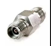
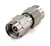
Male and male 2.4mm connectors
Because the mechanical structure of 2.4mm connector and SMA, 3.5mm and 2.92mm connector is not compatible, it is necessary to use precise adapter to fit them. For example:
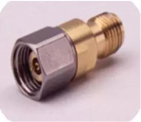
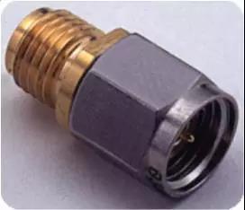
2.4mm Male to 3.5mm Female 2.4mm Male to 2.92mm Female
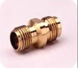
2.4mm Male to 2.92mm Female
1.85mm connector
The 1.85mm connector was developed and designed by HP in the 1880s with working frequency up to 65ghz. In 1988, its standard was published to promote the standardization of such connectors. The inner diameter of the outer conductor of the connector is 1.85mm, which can be directly mechanically interconnected with 2.4mm connector, but not with the SMA series connector.
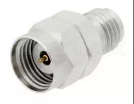
Female and male 1.86mm connector
V Precision Microwave Connectors
V Precision Microwave Connectors is another connector designed and developed by Wilton / Anritsu company in 1989. It uses HP's 1.85mm structure standard and can be directly connected with 2.4mm connector.
About 1.0 mm connector structure
The engineering of the modern millimeter wave industry and the need for test instruments have promoted the test bandwidth to W-band (70-110ghz), and it is not required to switch to the waveguide. The appearance of a 1.0mm connector structure meets this demand. The inner diameter of the outer conductor is very small, only 1.0mm.
1.0mm connector
1.0mm connector, born in the late 1880s, is developed and designed by HP (Agilent), with working bandwidth up to 110ghz. Laboratory technicians and engineers have begun to apply 1.0mm connectors to millimeter-wave analysis. Such connectors are also often used in semiconductor probe platforms to evaluate millimeter-wave RF MMICs. The use of 1.0mm coaxial connector greatly simplifies the multi-step waveguide-based test into one step. Same as above, because the outer conductor size is 1.0mm, it is called 1.0mm connector.
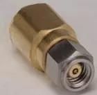
Agilent (HP) 1.0mm male connector
W connector
W connector was developed and designed by Wilton / Anritsu company in 1996, with working bandwidth up to 110ghz. Its characteristics and application are the same as HP's 1.0mmm connector.
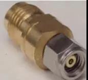
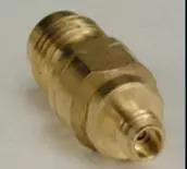
1.85mm female to 1.0mm male 1.85mm female to 1.0mm male
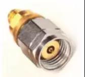
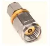
1.0mm Female to 1.85mm Male 1.0mm Female to 1.85mm Male
The mechanical structure of 1mm connector is not compatible with 2.4mm/1.85mm, so adapter is needed for adaptation, as shown below.
Even though most of the connectors are related to the inner diameter of the outer conductor, let's recognize them from the structure.
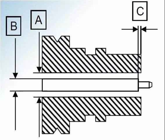
Schematic diagram of Male connector
Schematic diagram of Female connector
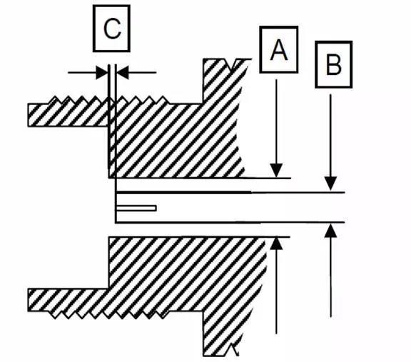
About the size of the joint:
A: inner diameter of the outer conductor (this parameter, the diameter of the central conductor and dielectric constant of insulating layer determine the maximum cut-off working frequency of this joint; many joint names are derived from this inner diameter index, such as 3.5mm, 2.92mm, 1.85mm, etc.)
B: outer diameter of the center conductor (the impedance of the joint can be determined by combining the inner diameter of the outer conductor)
C: clearance of the central conductor: it is very important to confirm that the clearance of the central conductor is within the index range, otherwise it may cause mechanical damage to the connector of the equipment or device.
Next, we will analyze the source of the name and the reason why it can be connected with each other from the structure of three common connector headers.
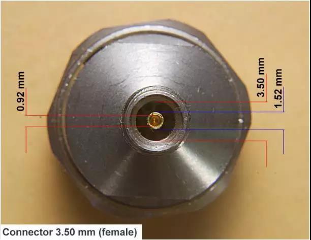
3.50mm connector
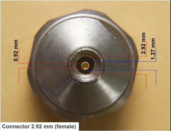
2.92mm connector
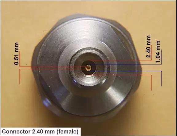
2.40mm connector
Referring to the above legend, the summary is as follows:
1. For SMA, 3.50mm, 2.92mm and K connectors, the inner diameter of the central conductor is the same, both of which are 0.92mm and can be interconnected.
2. For 2.40mm, 1.85mm and V connectors, the inner diameter of the central conductor is the same, both of which are 0.51mm and can be interconnected.
3. Due to the difference of inner conductor size design between 1.0mm male connector and W connector, 1.0mm male connector cannot be interconnected with W male connector, and 1.0mm male connector can be interconnected with W female connector.
4. 1.0mm female connector cannot be interconnected with W male connector.
Highest working frequency and interoperability of different types of connectors:
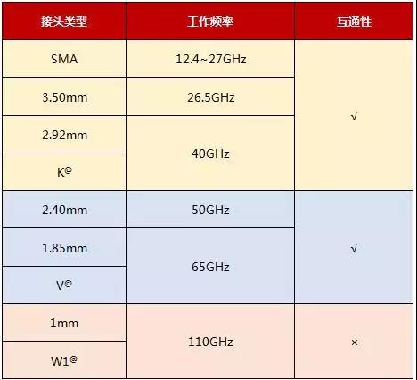
The inner conductor of HP's 1.0mm female connector has a hole design size of 0.27mm ± 0.013mm, while that of Wilton's W head has a center conductor outer diameter of 0.29mm ± 0.013mm or 0.32mm ± 0.013mm (low loss cable). The design sizes of the two are different. When a 1.0mm female connector is used to interconnect with w male connector, 1.0mm female connector will be damaged. Therefore, 1.0mm FEMA connector will be damaged The Le connector cannot interconnect with the w male connector.
To sum up, the connector precautions are summarized as follows:
1. The accuracy and firmness of mechanical interface are considered in the design of many coaxial connectors, but it is necessary to clean them frequently in use. At the same time, the torque added to the nut when tightening should also be appropriate to ensure the minimum distance between the shoulder of positive contact and the finger of negative contact. Only in this way can good signal connection characteristics be guaranteed.
2. When the SMA male connector is used to interconnect with the precision SMA male connector (3.5mm or 2.92mm) of the female connector, the professionalism of the manufacturer of the SMA male connector must be guaranteed, and the male connector must be connected in a positive and straight direction.
3. When using SMA cable, especially semi-rigid cable, please do not bend near the joint to prevent the length change caused by the center of the cable and damage the female connector connected with it.
4. 1.0mm female connector cannot be interconnected with W male connector.
Highest working frequency and interoperability of different types of connectors
Tips:
It is also very important to check and clean the connector regularly!
Inspection and cleaning procedures:
1. Use a 20x microscope to check the microwave connector;
2. If cleaning is required, please ensure that all equipment and operators are grounded;
3. Please avoid using connectors with mechanical damage (scratches on the connection surface, abnormal or bent central conductor);
4. Please use cotton swabs and anhydrous alcohol for cleaning. When cleaning the central conductor, excessive force or alcohol injected into the insulation body will cause damage;
5. All alcohol and dust particles must be blown clean with compressed air and sprayed vertically to prevent residues from remaining on the joint.
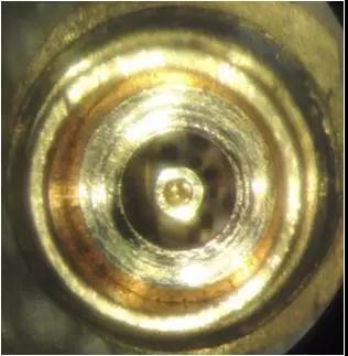
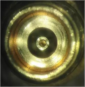
Unclean connector Connector after cleaning
(outer conductor contaminated) (outer conductor clean)


